Gravimetric feeding applications
Weigh belt and loss-in-weight (LIW) feeders are common choices for gravimetric feeding applications. Both types have their advantages, but the weigh belt feeder is often the go-to choice for handling difficult materials, space limitations, and other tough requirements. To understand why, let's start with a look at how each feeder operates.
Sponsored by

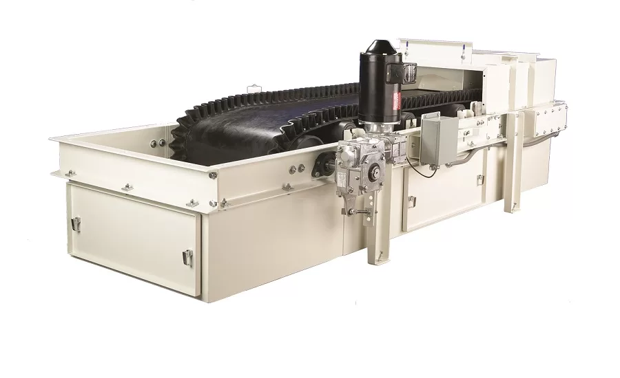
A weigh belt feeder typically consists of a short belt conveyor with an integrated weigh scale section. Its feed inlet is located under or in-line with an overhead supply bin (or volumetric pre-feeder), and a discharge is located at the feeder's opposite end. The weighed section is supported by a load-cell-based weighing platform, in which case the section is called a weigh deck, weighbridge, or slider deck; or the section can rest on idlers supported by load cells. The load cell and a tachometer are typically linked to a remotely located motor-speed controller and the feeder controller, which can be programmed with the feed rate set point. An adjustable vertical profile plate (also called an adjustable slide gate) is located between the feed inlet chute and the belt's feed end.
In operation, material from the supply bin discharges through the feed inlet onto the belt, which moves the material toward the weighed section. As the belt moves, the material is sheared by the vertical profile plate, which is adjusted to a height that controls the amount of material carried on the belt to maintain a constant belt load. The feeder controller integrates the load cell's weight signal with the tachometer's belt-speed signal, calculates the actual feed rate, compares it to the setpoint, and, if necessary, signals the motor to speed up or slow down to match the setpoint.
A LIW feeder is an integrated unit that commonly includes a hopper, a feeding device (usually a screw feeding device consisting of a screw housed in a feed tube) mounted below the hopper, and a scale that either supports or suspends the hopper. 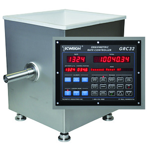 A feeder controller is located outside the unit. A flexible connection attaches the LIW feeder to a refill device (such as a screw feeder or rotary airlock valve) that's located below a refill (or supply) bin's outlet and above the hopper's inlet.
In operation, material discharges from the hopper into the screw feeding device, which dispenses the material at a controlled rate. The feeder controller, which has been programmed with the feed rate setpoint, receives weight readings from the scale and calculates the hopper's loss in weight per unit time. The controller compares this with the feed rate setpoint and, if necessary, signals the screw feeding device's variable-speed drive to speed up or slow down to match the setpoint. Before the hopper runs out of material, it's reloaded as quickly as possible to a preset level by the refill device; because the LIW feeder won't be able to sense loss in weight while it's refilling, it switches from gravimetric to volumetric control during this step.
Handling a material with a particle size larger than about ¼ inch, such as aggregate, creates problems for an LIW feeder with a screw feeding device. While the clearance between the rotating screw's outside diameter and the feed tube's inside diameter is normally about ⅛ inch, this can decrease at many times during feeding, creating metal-to-metal contact at pinch or binding point between the screw and the wall. Very large particles can become caught in these pinch points, not only stopping the feeding process but twisting or breaking the screw, causing it to seize.
In contrast, a weigh belt feeder can handle materials with very large particles, such as limestone, rocks, cornhusks, and waste materials, without binding. This feeder draws material from the supply bin, and the vertical profile plate can be adjusted to accommodate large particles, allowing the material to slide under the plate and feed continuously without interruptions. (As a rule of thumb, the profile plate should be adjusted to a height about three times the largest particle size.)